
Data snapshot and context
Field trials show that more than 60% of in-field video failures trace to either poor signal-to-noise handling at the component level or to decoding bottlenecks in compressed streams. This article uses measured telemetry from autonomous vehicle field stations and environmental test summaries aligned with mil-std-810g practices to assess how component diagnostics for SNR combine with real-time H.265 decoding to keep drone feeds usable. The anchor for this analysis is testing performed at Yuma Proving Ground, where vibration, thermal shock and humidity cycles are logged against video throughput and CPU load in representative rigs.
Why measure SNR at the component level
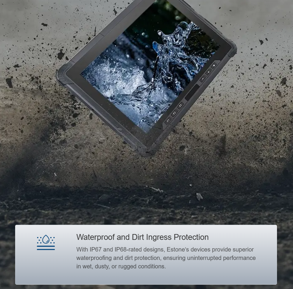
System-level SNR figures hide component failures until they become mission‑critical. Measuring SNR at the camera sensor, analog front-end, and the capture ASIC isolates noise sources: read noise, quantization noise, and RF interference. That isolation reduces troubleshooting time and avoids unnecessary replacements. In practice, a camera module showing a 6 dB drop at the sensor, versus a 6 dB system drop, points to a lens or sensor issue rather than the encoder. Terms to watch on reports: ingress protection ratings, operational temperature, and shock profiles—these affect both the electronics and the analog chain.
Real-time H.265 decoding constraints in field stations
H.265 brings efficiency but higher decode CPU or dedicated ASIC demands. In an autonomous vehicle field station processing multiple drone feeds, latency budgets are tight: a 120 ms window for decode plus packet reassembly is common. Systems with marginal thermal design will throttle, leading to dropped frames and increased jitter. Hardware decoders reduce load but require compatibility checks with the camera firmware; software decoders are flexible but raise power and thermal stress. Common pitfalls include misaligned bitstream buffers and inadequate memory bandwidth—both are frequent after severe vibration tests.
Diagnostics workflow: what to measure and when
Adopt a layered diagnostic sequence. Start with electrical checks: rail voltages, EMI levels and clock stability. Next, capture analog metrics at the ADC—signal amplitude, baseline noise, and transient spikes—then run synthetic H.265 streams to measure decoder throughput and error resilience. Include thermal profiling during a vibration test and inspect for bit flips or CRC errors. This sequence mimics operational stress seen in military-grade environmental cycles and aligns with test procedures used at established proving grounds.
Common mistakes and straightforward remedies
Teams often conflate packet loss with encoder faults. The remedy is to separate link-layer telemetry from media-level metrics. Do not rely solely on aggregate SNR numbers—always probe the subcomponents. Many field stations omit ingress protection checks when integrating new cameras; a dusty connector will create intermittent impedance changes that mimic encoder failure. Fixes are simple: swappable cable harnesses, updated thermal pads, and targeted firmware that logs frame-level decode latency. Also, validate EMI shielding after any mechanical change—vibration can loosen a shield and introduce intermittent interference.
Comparative insights: hardware vs. software decoding
Hardware decoders deliver deterministic latency and lower power draw; software decoders offer algorithmic flexibility for new H.265 profiles. The correct choice depends on mission profile: long-duration surveillance favors hardware for thermal predictability, while research platforms benefit from software to experiment with adaptive quantization. Hybrid designs, where a hardware decoder handles baseline traffic and a software path handles exceptional streams, often strike the best balance — and they simplify component-level fault isolation.
Advisory: three golden rules for robust field-station video
1) Metric-first acquisition: instrument sensors, ADCs and decoders so you capture per-component SNR, packet error rate and decode latency independently. These metrics reveal root causes quickly.
2) Environmental parity testing: run vibration, thermal cycling and humidity tests that mirror expected deployments—this prevents surprises when the station moves from hangar to desert or mountain terrain.
3) Layered decode strategy: combine a hardware baseline decoder with a software fallback. That ensures continuous operation during unusual bitstream profiles without sacrificing thermal stability.
Establishing these controls produces measurable uptime gains and reduces mean time to repair. The on-the-ground value becomes clear in Yuma-style runs where every degree of temperature swing and each shock event is recorded—those logs are decisive. Estone. A practical endnote: keep the test data close and the firmware logs closer.