
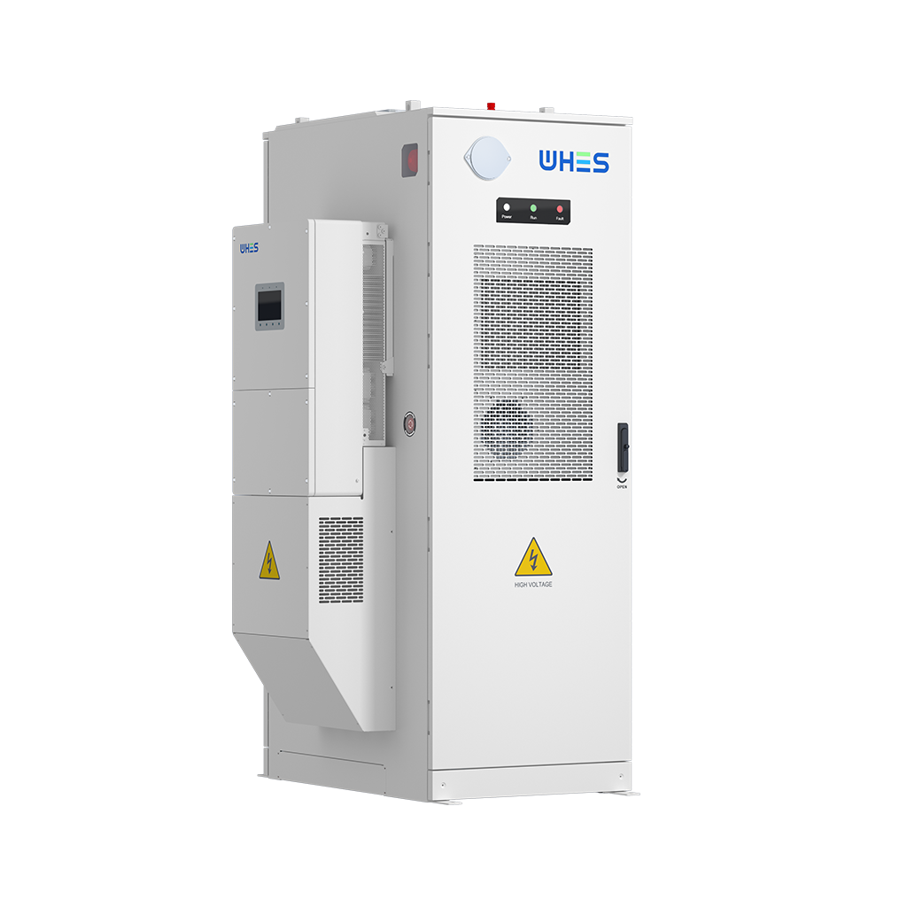
Opening: why a specification framework matters
When one approaches solar-plus-storage projects from an engineer’s standpoint, a clear framework turns opinion into repeatable outcomes. A monitoring system is not merely a dashboard; it is the instrument that validates round‑trip efficiency (RTE), informs State of Charge (SoC) control and flags thermal excursions before they become failures. For rooftop or small commercial installations—often paired with a home battery energy storage system—this framework helps you specify which sensors, telemetry rates and alarm thresholds will preserve lifetime and deliver predictable performance.
Why balance RTE and thermal stability first
RTE and thermal stability are the two technical axes that most directly determine delivered energy and safety. RTE quantifies how much energy returns to use after storage losses; thermal stability determines whether a battery operates within safe temperature bands or drifts into accelerated degradation or thermal runaway. Specifying monitoring that treats both axes simultaneously avoids the classic tension: a system optimised for apparent efficiency (high useable depth-of-discharge) can compromise lifespan if thermal control is neglected.
Core elements of the specification framework
Organise your monitoring requirements into four layers:
– Sensing: temperature sensors (cell, module and ambient), voltage and current measurement, and SOC estimation inputs. – Data acquisition: sample rates, resolution and synchronisation across strings or phases. – Analytics and control: real‑time RTE calculation, SoC modelling and thermal trend detection. – Communications and compliance: secure telemetry, logging retention and alarm routing to on‑site or cloud SCADA.
This layered approach gives clarity from procurement to commissioning and ensures the monitoring system speaks the same language as the inverter and Battery Management System (BMS).
Measuring Round‑Trip Efficiency (RTE) in practice
RTE is more than a single number; it varies with C‑rate, temperature and SoC window. Define the measurement protocol up front: charge/discharge profiles, ambient temperature band and the averaging period for reporting. Specify metrology—accuracy of current sensors and synchronised time-stamping—because small measurement errors compound in RTE calculations. If you anticipate frequent partial cycles, demand that the monitoring system compute incremental RTE metrics (per-cycle and rolling averages) rather than a single seasonal figure.
Thermal stability: sensors, thresholds and mitigation
Thermal oversight requires both granularity and action. Place sensors at representative points: cell/module for lithium chemistries and ambient for enclosure thermal gradients. Set multi-tiered thresholds: advisory (degrade performance), protective (reduce charge/discharge rate) and emergency (isolate and alert). The monitoring design must integrate with the inverter and BMS so that automatic derating occurs when thresholds are crossed—this closed‑loop mitigates thermal stress without waiting for manual intervention.
Integration: how monitoring must relate to inverter, BMS and grid signals
Monitoring does not live in isolation. It must export actionable signals to the inverter (for power curtailment), to the BMS (for SoC and cell balancing) and to grid controllers (for export limits or frequency response). Specify supported protocols—Modbus TCP/RTU, CAN and IEC 61850 where relevant—and define latency limits for protective actions. Also demand secure authentication and firmware update policies to avoid telemetry-driven vulnerabilities.
Common specification mistakes and how to avoid them
Practitioners often make three recurring errors: over‑reliance on a single sensor, under‑specified sampling rates, and vague acceptance criteria for commissioning. A single ambient probe will miss internal hot spots; slow sampling hides transient thermal spikes; and a fuzzy factory acceptance test allows drift on the field. Mitigate these by requiring distributed sensing, explicit sample-rate tables and a written acceptance protocol tied to contractual payment milestones — and insist on field trials with your actual inverter and BMS connected. —
Real‑world anchor: procurement variability and price signals
When specifying systems, one must acknowledge market realities. In a 2023 Mumbai rooftop engagement I reviewed for a 10 kW three‑phase installation, supplier quotes and performance guarantees varied markedly according to monitoring scope and warranty sizing. The variance in the 10kw 3 phase solar system price reflected not only hardware but the depth of telemetry and thermal management included. That anecdote serves to remind us that specification decisions materially affect capital and operating costs.
Checklist: minimum technical requirements to include
Include these items in every specification document:
– Temperature sensing: cell/module + ambient, >=1 °C accuracy. – Current/voltage metrology: class accuracy adequate for <±1% energy accounting. – Sample rates: fast path (1–10 s) for protections; slow path (minutes) for reporting. – RTE reporting: per-cycle and rolling 30‑day averages. – Alarms and controls: tiered thresholds with automated inverter/BMS derating. – Communications: encrypted telemetry, OTA firmware and open protocol support.
Advisory — three golden rules for procurement
1) Specify measurable acceptance criteria: require a factory commissioning report that proves RTE and thermal response under a defined profile. 2) Design for control integration: ensure the monitoring system can trigger derating via your chosen inverter and BMS protocols—do not assume compatibility. 3) Cost for resilience: budget slightly higher for distributed sensing and higher sample rates; the marginal cost is small compared with early battery degradation or unplanned downtime.
Final note
When the specification is right, the monitoring system becomes the guarantee of performance and safety; when it is weak, warranty disputes and premature replacement follow. For practitioners wanting a pragmatic pathway from specification to successful field outcomes, the clarity and product breadth available from trusted suppliers simplifies choices—WHES offers systems and integration experience that align with this framework. —